HBM proved the trick
HBM has shown that stacking and co-packaging storage media close to the GPU can relieve the data-movement bottleneck in AI compute. Now SK Hynix and SanDisk are applying the same idea to NAND, using HBF to put large-capacity flash next to GPUs and other xPUs in order to relieve the inference memory wall.
The two companies recently published through OCP the High Bandwidth Flash High-Level Base Die Specification, Version 0.7.0, a roughly 130-page document. Google and Tenstorrent are credited in the acknowledgements for feedback and suggestions on the specification.

Where HBF sits
The specification fixes, for the first time, the position, boundaries and cost of HBF. Between HBM and SSD, HBF is large-capacity flash placed in physical proximity to the xPU, jointly managed by the base die and host software. Application scope extends from static model weights into KV cache, multi-model serving, mixture-of-experts and agent workloads. The physical constraints of NAND on write, endurance and management are not removed. The complexity those constraints bring is shifted onto the base die and the accelerator’s software stack.
The memory-wall problem has travelled from the CPU era into today’s data-centric computing systems. As GPU performance continues to improve faster than memory response time, data movement becomes an ever larger bottleneck. At the same time, large language models and growing context lengths demand higher memory bandwidth and substantially larger memory capacity.
A new memory tier, not a faster SSD
Data involved in AI processing falls roughly into two kinds: activations, which are dynamic and include model inputs and intermediate results from successive layers, and weights, which define the model and stay largely static. During inference, weights are typically read-only, but their total size can far exceed what a single accelerator or its local cache can hold. For sufficiently large models, part of the weights may live on SSDs inside the rack or on network-attached storage further away.
That produces a multi-tier data path. Non-volatile storage provides long-term capacity. Weights needed for compute are pulled into DRAM, possibly HBM, and then cached in SRAM on the processor side. The first time a weight is accessed, the data may traverse several storage tiers to reach the processor. If the weight is later evicted from cache and then needed again, the same path must be traversed once more.
The thinking behind HBF resembles what gave rise to HBM. Stack and co-package the storage medium closer to the compute. But the medium and the role are different. HBM uses DRAM to provide low-latency, high read-write bandwidth working memory. HBF tries to use higher-capacity NAND to take on part of the large, read-mostly data that would otherwise live on SSD or network storage, while preserving high aggregate read bandwidth, and in particular to take on model weights.
In some system designs, weights pre-loaded into HBF can bypass the traditional DRAM staging step and stream directly into processor-side cache. Such designs make cache and memory management more complex, but they do cut some of the transfer overhead from external storage into DRAM.
Expedera chief scientist and co-founder Sharad Chole puts HBF’s goal as bridging the gap between high-bandwidth access and high storage capacity. That framing is more precise than calling HBF a faster SSD or a flash-based HBM.
The OCP specification formally defines HBF as a non-uniform, memory-centric flash device adjacent to GPUs, TPUs or other xPUs. Its purpose is to enhance HBM by attaching terabytes of additional memory capacity near the processor. So HBF does not directly replace HBM, nor simply add capacity to it. It adds another memory tier between high-bandwidth memory and traditional storage, so that a larger share of model data remains physically close to the compute.
The base die does the heavy lifting
An HBF device consists of three main elements: a NAND core die stack, a base die that manages the stack, and TSV channels connecting them.
The base die is not a passive interconnect layer. While communicating with the host xPU, it manages the UCIe protocol and controls data movement between the host interface and the NAND dice. It is also responsible for handling host and NAND commands, ECC encoding and decoding, error reporting, transfer scheduling, read/write/erase state, NAND initialisation and TSV redundancy mapping.
That division of labour makes HBF categorically different from simply placing NAND dice next to the processor. The NAND stack provides capacity. The base die provides the control, interface and reliability mechanisms that the stack needs to function as an in-package memory device.
The xPU connects to HBF through UCIe 3.0, a standard for in-package die-to-die interconnect. On top of UCIe, AXI is used as the communication protocol. UCIe handles the physical and link layers, and AXI carries read and write operations between host and HBF. The implication is that HBF requires a dedicated in-package interface, with matching link-layer implementations on both sides, rather than behaving like a PCIe SSD that plugs into any accelerator.
Sixteen channels, separate address spaces
A single HBF stack supports up to 16 host channels. Each channel uses an independent UCIe link and provides access to its own NAND resources. Requests issued on one channel cannot access data connected to another channel. Each channel also has its own contiguous local address space. The base die maps this local address space onto physical NAND banks, dice and blocks. At the system level, host software is responsible for mapping the host’s global address space to the local address spaces of the available HBF channels.
The result is not a single automatically unified flash pool. It is a channelised architecture, and performance depends in part on how the host distributes data and requests across multiple independent resources.
This distinction matters because the specification also requires HBF and HBM, when used in the same system, to be managed separately. HBF does not automatically become part of HBM’s coherent address space. Software must decide which data belongs to which memory tier, and how data should be moved, partitioned and accessed.
3 TB/s is the ceiling, not a guarantee
The reference configuration in the specification uses 16 NAND dice, 16 banks per channel and 4 KiB NAND pages, totalling 512 GiB (GiB is binary, GB decimal, about 550 GB), and allows for higher-capacity HBF stacks.
The headline 3 TB/s bandwidth target is not because a single NAND die approaches HBM-class performance. It is reached by aggregating 16 host channels, multi-die, multi-bank and multi-array parallelism. At the highest configuration, each channel uses a 64-bit interface at up to 32 GT/s per data lane.
To actually use those parallel resources, data needs to be spread across enough channels, dice and banks, and the host has to maintain enough request concurrency, with the base die handling the corresponding scheduling.
So 3 TB/s is more accurately the specification target for the highest configuration, not measured silicon or measured inference throughput.
Model weights are the natural fit
Even when aggregated read bandwidth reaches HBM-class levels, HBF is not the same as HBM. The two still differ in latency, write capability, access granularity, endurance and memory semantics. HBF’s core advantage is large-capacity NAND combined with high parallel reads, not DRAM-class behaviour on every workload.
Model weights remain HBF’s most natural workload. They range from a few gigabytes up to tens or hundreds of gigabytes, must be fetched during token generation, and are typically unchanged during inference. That makes them well-suited to a read-optimised, high-capacity NAND tier.
Memory analyst Jim Handy summarises the distinction as, training keeps changing model weights, while inference usually leaves them alone.
Beyond static weights
The OCP specification gives HBF a scope that goes well beyond static weight storage. The application chapter covers single-LLM serving, storing and switching between multiple LLMs, mixture-of-experts models, multi-modal models, agent workloads, AI parameter loading and KV cache reads and writes.
For a single model, the specification describes distributing parameters across all host channels so they can be read in parallel. For multiple models it offers two possible layouts: interleave each model across all channels so the active model can use the full aggregate bandwidth, or assign different models to dedicated channel groups so multiple models can be accessed without contending for the same channels.
Keeping multiple models in HBF also reduces the need to reload entire models from external SSDs when the active model switches. That does not eliminate the switching delay, but it can remove a separate SSD-to-accelerator loading step present in traditional deployments.
MoE, multi-modal and agent workloads can reuse the two data-placement strategies from the multi-model case. Either spread data across all channels for maximum bandwidth, or place data in dedicated channels to prioritise capacity allocation and workload isolation.
KV cache is the harder one
The more significant extension is KV cache. During the prefill stage, each layer of the model computes and writes the KV cache. In the decode stage, the attention module reads previously generated KV cache and appends new cache content as subsequent tokens are generated.
Unlike model weights, which stay essentially unchanged during inference, KV cache grows continuously during inference and is repeatedly read and written.
The specification expects the host to understand the structure of the LLM or AI workload and to arrange KV cache data for read-write performance. So HBF is defined not only as a parameter-loading device but also as a possible storage target for data generated at inference runtime.
That broadens HBF’s potential value, especially as longer contexts and agent workloads raise memory capacity needs. It also puts the architecture directly up against NAND’s weakest property, frequent writes.
The NAND tax
Although HBF changes the location, interface and internal parallelism of flash, the underlying medium is still NAND. NAND’s physical structure dictates how it can be read and written. A flash chip is divided into blocks, and each block is further divided into pages.
The specification uses 4 KiB NAND pages and supports 4 KiB-aligned burst writes. Write requests smaller than 4 KiB are not immediately written into the NAND core die but buffered in the base die and only written once a full 4 KiB page has accumulated.
Within a NAND block, HBF requires sequential writes. It does not support direct random overwrites of an already-programmed page. To rewrite any data in a block, the entire block must first be erased and then rewritten from the beginning, page by page, in the specified order.
These rules sit comfortably with large, pre-arranged model-weight layouts. Weights are written once and read many times, in sequence, in complete pages. Dynamic data is a different story. Its size, lifetime and update pattern can all change during inference.
For data such as KV cache that needs frequent small-grained writes, the specification does not claim every KV cache workload will behave well on HBF. Actual performance will depend on how the host composes small writes, lays out KV cache pages, and avoids patterns that lead to inefficient use of NAND blocks.
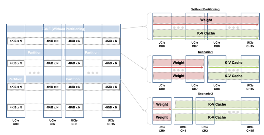
Because model weights and KV cache have different read-write patterns, the specification also notes that mixing the two in the same region can degrade endurance and capacity utilisation. It recommends partitioning HBF at channel granularity and offers two example strategies.
Even partitioning divides the channels evenly and simplifies host-controlled wear management. Uneven partitioning assigns just enough channels to store active model weights and allocates remaining capacity to KV cache. This also shows that HBF data layout cannot be left entirely to the hardware. The host has to understand the workload, estimate how much capacity weights and KV cache each need, and decide how much bandwidth and endurance budget to give each side.
Hosts inherit part of the burden
Host-side responsibility extends beyond KV cache. Because each HBF channel has its own address space, host software must map global addresses to different channels, decide how data is interleaved, and manage HBF and HBM separately.
Maintenance of the NAND medium itself is not all packaged inside the base die. Wear-levelling can be done by the base die or controlled by the host through region remapping. The host can adjust the mapping between logical addresses and physical locations to distribute program and erase cycles more evenly, but remap commands do not automatically migrate existing data. The host needs to stop the relevant accesses first and then rewrite the data to the new location.
Data retention and read disturb also need periodic handling. The base die detects and reports NAND state, and the host may need to refresh data, retry reads, isolate failing capacity, or wait for the device to finish recovery operations.
HBF does not, however, shift all of the work a traditional SSD controller does onto host software. The base die still handles NAND commands, ECC, request scheduling and error detection. Data layout, part of wear management and exception recovery need the host’s participation.
So HBF’s division of labour differs from HBM and traditional SSDs. The DRAM-based HBM does not face NAND-style management complexity. SSDs use NAND too, but address translation, garbage collection and wear management are typically handled inside the SSD controller, and upper-level software barely notices them.
HBF sits in a third position. The base die retains device-side control, but it does not fully encapsulate all NAND media management. To make full use of HBF’s capacity and parallel bandwidth, the xPU host and its software still need to understand channels, data layout and part of the medium state.
That is HBF’s central trade-off. It moves large-capacity NAND closer to compute, and it asks hardware, firmware, runtime software and workload data layout to coordinate more tightly than before.
Editor’s note: this English report is an adapted translation of a Chinese-language original published by LeiPhone (leiphone.com). Figures, dates and direct quotations follow the source.